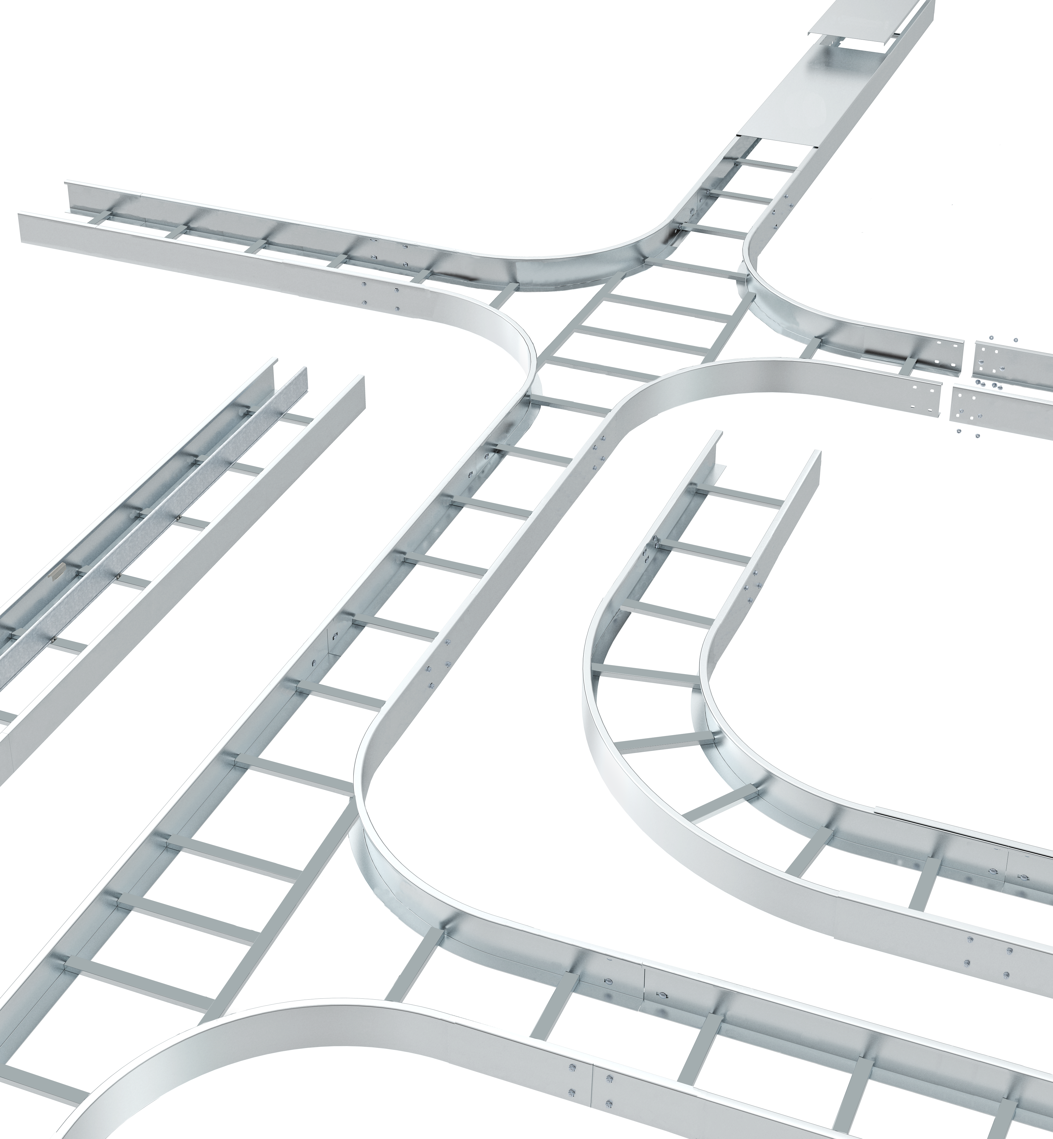
Ladder Tray
When metal ladder cable trays came of age, they were used to support the new armored shielded power cables that were permitted outside the conduit environment. Utilities and industrial companies initiated the use of expanded metal and solid trough-styled trays for supporting power and control cable.
Cable trays quickly proved their worth as a safe, dependable and cost-effective solution to routing and supporting cables. Installed cost savings of over 50% on project after project drove the market for metal cable trays to over 80 million dollars.
Cable Tray is NOT A WIREWAY and is viewed as a support for cables. This provides the designer and user with many benefits.
- Full free air rating of cables results in smaller conductors vs. conduit
- Greater fill volume allowed results in less space
- Used in all locations except elevator shafts (the only prohibition on cable tray use)
- Used as an equipment grounding conductor (classified by UL)
- Less stress on cables during installation and operation
- Increased safety, no moisture condensation problems nor transmission of corrosive or explosive gases, as with conduit
- Simplified maintenance with the flexibility of adding or changing circuits
- Simplified engineering and construction. Add, change, modify more easily
- Used with other wiring methods
- Longer support spans up to 55' (Chalfant's standard system to 40')
Selecting the Right Ladder Tray
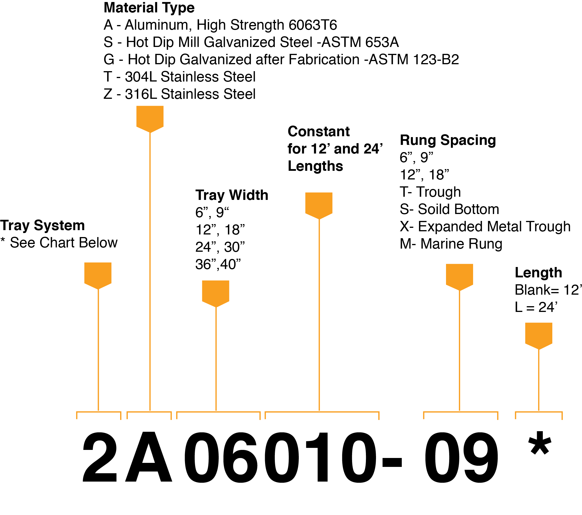
1 Determine the Type of Tray - Ladder type cable tray can support heavy power cables or small circuit size communication cables for control data and phone cables or a mix.
- Rung Spacing: Single conductor over 4/0 and MC cables should be used with 12" or 18" rung spacing. Smaller diameter cables require 6" or 9" rung spacing.
- Tray Bottom: Trough, solid or ventilated type trays offer protection and better support for small lightweight instrument or data cables.
- Barrier Strips and Covers: Barrier strips can be used to separate voltages or power and control cables to avoid the cost of adding a second or separate tray for each. Covers are not required by the NEC but should be considered for the protection of personnel and any debris or other material that could fall into the tray.
2 Select Metal and/or Material Finish - The job site and its' environment will determine which metal and/or finish is required. Review where the tray is being used. Are there unusual corrosive conditions (like those found in some chemical and paper processing plants)?
- Aluminum (High Strength 6063T6 Extrusions, 5052H34 Sheet) - Most conditions are satisfied by aluminum tray, which lends to its popularity. It is less expensive and easier to install than galvanized steel and its finish is smooth and consistent. Longer span trays are also available in aluminum. It is ideal for seacoast, offshore and most petrochemical and pulp mill applications.
- Galvanized Steel (Mill Galv ASTM 653A / Hot Dipp Galv after Fabrication ASTM 123-B2) - Hot dipped galvanized steel is used in outdoor, chlorine, acid, and caustic areas. Mill galvanized is less expensive and only recommended for indoor applications.
- Stainless Steel (304L and 316L) - Stainless Steel trays are used in special highly corrosive environments and compare favorably with fiberglass type ladder trays.
3 Determine Type of Support - Review the various support methods and options and calculate the distance between supports, know as the "support span".
You can support your cable tray system:
- from walls or vertical columns with shelf or cantilever brackets
- with trapeze or single supports using threaded rods hung directly from building steel
- on or under pipe racks, trestles or bridges
- in utility trenches, tunnels or directly on roofs
Hint: You can save money by using a heavier duty tray that results in longer spans and reduces the number of costly supports and installation time. A heavier duty tray will also provide a deeper loading depth and a stronger, less deflective, long-span support.
3 Determine Cable Load - Review the number and type of cable(s) form the job descriptions and requirements. "Cable fill" in a tray is calculated by using data and criteria specified in NEC 392. To determine the total "cable weight", add all cables on a lb/ft basis.
- Data, telephone and instrument cable should be calculated to fill the tray to 50% of the tray cross-section fill area (40% for solid bottom tray). in reality, because of voids, overlapping the circular shape of the cable, a 50% fill will appear to completely fill the cable tray.
- MC cable 4/0 or larger, rated 2000 Volts or less, can only be installed in one layer (sum of cable diameters equals tray width).
- Single conductor 2000 Volts or less, larger than 1000 KCM can only be installed in one layer (sum of cable diameters equals tray width).
- Other power cables and combinations of sizes are calculated on the sum of cable areas versus allowable fill, see table in NEC 392.9 to determine tray width. NEC 392 details cable types, voltages, ampacity, etc.
Other Loads to be Calculated -
- Snow: Add 13.3 lbs/ square feet for 20-inch deep wet snow.
- Ice: Add 4.7 lbs/square feet
- Concentrated Load: Add load effect for concentrated load effect from splice boxes, heavy cable drop outs and conduit terminations supported off the tray.
Once you have determined your worst caseload, add it to your other cable load calculations. You now have the maximum load the tray must support.